Stepper Motor Controller Code Update

October 15th, 2009

Just a quick update, I’ve added support for limit switches in the firmware. Enable them by specifying the associated pin, and if it’s active high or active low.  The preferred method is active low otherwise you need to add your own pulldown resistor if it’s active high.

// specify min-max sense pins or 0 if not used
// specify if the pin is to to detect a switch closing when
// the signal is high using the syntax
// #define MIN_X 12 | ACTIVE_HIGH
// or to sense a low signal (preferred!!!)
// #define MIN_Y 13 | ACTIVE_LOW
// active low is preferred as it will cause the AVR to use it's internal pullups to
// avoid bounce on the line.  If you want active_high, then you must add external pulldowns
// to avoid false signals.
#define ACTIVE_HIGH _BV(7)
#define ACTIVE_LOW  _BV(6)
#define MIN_X 0
#define MAX_X 0
#define MIN_Y 0
#define MAX_Y 0
#define MIN_Z 0
#define MAX_Z 0

Electronics ,

Stepper Motor Controller Update

October 5th, 2009

I’ve recently posted about my new stepper motor controller. Well, I was unhappy with the implementation used in the RepRap project, and what started as a code cleanup has turned into a near full rewrite. I’m fairly happy with the code now and finished my preliminary testing. I based my original version of the re-written code turned out to be a variant of Bresenham’s algorithm (though I found this out after I had written the code). The algorythm would determine the axis which required the most travel, step that axis, then add the required travel from one of the other axis to an error term for that axis. When the error term was equal to or greater than one, it would step that axis and subtract one from the error term. This resulted in stepping synchronized with the major axis timebase. Looking at the output of the stepper motor driver, this pattern emerged.

steppring rates.jpg

Here the G-Code command was “G1 X3 Y2 Z1” — and indeed the ratio of steps is 3:2:1, but notice that the Y-steps are required to align with the X-Steps (master axis because it moves the furthest), but because 3 is not divisible by 2, it skips every third step. This motion is bad for the stepper motor, and it can cause all sorts of problems.

It is *extremely* important the steps be evenly spaced, unless you’ll be content with slow, unreliable operation. Jitter in the step pulse train will limit your top speed, as it *will* cause the stepper to stall. -Ray L.

So I spent some time thinking about it, and came to the conclusion that the Bresenham’s Algorithm only makes sense if you are dealing with a pixelated output (its main purpose is for fast rendering of lines on computer screens). I realized that I needed was a temporal based one, and came up with something. I still need to do a literature search to see if someone has come up with it yet (would be surprising if no one has) but this is basically what I came up with.

  1. Determine the number of steps per axis
  2. Determine the distance of travel for the command, and based on the feedrate, compute the duration of the command.
  3. Compute the time between steps (TBS) for each axis (duration / steps)
  4. Start the main loop.
    1. If the time elapsed is equal to 1/2 the TBS, then step that particular axis.
    2. Wait 1/2 TBS, then go to step 5.

I prototyped this in python, and came up with

maxtime = 100.0; #duration of motion in microseconds
steps = 41.0;  #number of y steps
timePERstep = maxtime/steps; #time per step
y=0;
stepped = 0;
oldTimeIntoSlice = 0;
for time in range(0,int(maxtime)):
        timeIntoSlice = (time%timePERstep);
        if (timeIntoSlice < oldTimeIntoSlice):
                stepped = 0;
        oldTimeIntoSlice = timeIntoSlice
        if (timeIntoSlice >= 0.5*timePERstep) and (stepped == 0):
                        #print 'step'
                        stepped = 1;
                        y = y + 1;
        print '%d,%d' % (time,y)

Which generated this sort of a stepping profile. Notice that the steps are pretty evenly spread out..

temporal.jpg

After rewriting the arduino code, I tried the same test (with G1 X1 Y2 Z3 this time) and got much better results

temporal stepping.jpg

Notice how everything is nicely spread out. Looking at the timestamps, the maximum step jitter is about 150uS. The next step is to hook this up to some stepper motors and see what it does.

I’ve also released the code for the arduino here in case it might be of help to anyone. I’m thinking of making a daughter board for the arduino with the stepper controller ICs on it in order to simplify deployment for others — if there is interest.

Electronics , , , , ,

Arduino-Based Stepper Motor Controller

September 24th, 2009

P1030113.jpg

P1030118.jpg

Decided to drop my PCB and use some prebuilt modules from pololu. Doing the math, this turned out to be the cheapest option (3x$13 vs. $50 for the PCB plus another $30-$50 to populate). The pololu modules use Allegro’s A4983 intgrated h-bridge drivers rated at up to 2A – which amazes me given the size of the ICs. I’m a bit worried but I suspect that they’ve already been tested. I’m going to power it with a +/- 15V 3A supply I have, and use the g-code parser from the reprap project.

Electronics , , ,

A little bit steampunk

September 22nd, 2009

P1030110_Medium.jpg

Anyone want to guess what I’m building now?

Electronics, Personal , , ,

Mood Rock

September 19th, 2009

I was in an art store and came across a neat looking alabaster rock.

P1030107.jpg

And for some reason, I thought it would be cool to stick some lights in it, which started yet another project. I started out by building a circuit on the cheap using some components I had lying around.

P1030059.jpg

P1030060.jpg

I thought it would be cool to control the color from the PC, so I decided to check out the AVR-USB project. The cool thing about AVR-USB is that it handles the USB protocol in firmware alone and doesn’t require any additional ICs. I had a number of hickups – the biggest one being that as soon as a USB packet was received, the SPI on the AVR would stop working. After many hours of not being able to figure out the culprit, I resorted to bit-bang SPI and everything started working. The lights are shiftbrites from macetech. The cable is an ISP programming interface for the AVR. Component count is fairly low – a crystal, a bypass cap, a supply cap, two USB termination resistors and a pullup resistor.

I used a masonry bit to drill a lot of holes in the bottom of the rock, then used a hammer and chisel to finish enlarging the space. The board just barley fits in there.

P1030062.jpg

And the effects were pretty cool..

P1030066.jpg

P1030065.jpg

The communication is via a modified hidtool.c application (an example shipped with AVR-USB) which transmits a 4 byte payload which is then shifted onto the LEDs. For completeness, I wrote a small application in perl to act as a webserver and handle requests – forwarding valid requests to the hidtool application. And I also put together a nice color picker front end which uses AJAX to update the color on the fly. So as you move the color picker, the rock changes color accordingly. I put together a video of everything working together here :

There is a small amount of lag, which is to be expected — the chain of operations is…

  1. open web app, and pick a color
  2. color picker uses AJAX to send requests to a server running on my desktop
  3. server forks hidtool.exe with the color arguments
  4. hidtool then connects to the USB device (rock) and transmits the new color strings.

This chain of events is repeated every time the color changes – this happens as the cursor is being moved around thus it can generate quite a few requests. To improve throughput, I would need to merge the C app into the perl app, or visa-vera.

I’ve gone ahead and put the application online here so go ahead and set your mood color which will be displayed on my rock.

Live Feed

This image is updated every 5 seconds.  Or go here.

Resources

Electronics , , , , , ,

Nixie Tubes

September 14th, 2009

nixie0001.jpg

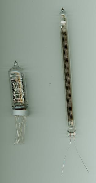
My nixie tubes arrived today from Russia. Trying to decide what to make with them. Any ideas? The one on the left displays numerals, and the one on the right is bar graph. I have 10 of each. I was thinking of perhaps a 10 channel spectral analyzer for my stereo with the bar graphs. A lot of people make clocks with the tubes on the left, but that seems almost a bit too generic.

Electronics ,

Stepper Motor Controller – USB interface

September 1st, 2009

stepper.jpg

I just finished designing a Stepper Motor Controller (SMC) for a PCB Mill that I ordered. One requirement most SMCs have is the need for a real-time operating system running only the milling software. This is because each motor movement must be timed precisely to ensure an accurate rate of movement from the milling head. If other software is running, then the timing of the interrupts can be off resulting in errors on the mill.

Not wanting to use a dedicated computer, I decided to design a bipolar chopper controller for myself. The big difference with this device and other controllers is that you will be able to feed it g-code directly, and not worry about controlling the timing. The processor onboard will be able to deal with the timing requirements and it should work. Some features include :

  • Send g-code directly via USB interface (linux/mac/winblowz drivers), does not require dedicated PC
  • Software controllable current (chopper mode) (1.5A/motor max)
  • 3-Axis on small PCB (2.9″x2.2″)
  • USB interface, powered off USB except for motor.
  • Over-temperature monitoring

If there is any interest, I’m happy to release the designs to the public domain.

Electronics , , ,

Yet another hobby: Silkscreening

August 30th, 2009

I was in an art supply store with Sarah and came across some supplies for screen printing so I thought I would give it a go. Turned out that the instructions weren’t so great. As they say, third time is the charm – the first two attempts I had overexposed the screen. The instructions said 1.5 hours with a 150W bulb. Turns out that 20 minutes with a 75W flood light is all that is required. The paint also requires an iron to set, which is a technology I do not believe in. So I used my 1375W hot air gun, which seemed to work fine (I applied for 30 seconds vs. 3-5 minutes with the iron). I went with an homage to Team America.

P1030056_Medium.jpg

Personal , , ,

CO2 Sensor Distraction

August 21st, 2009

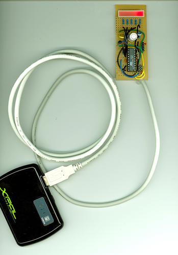
Many hours ago I got sidetracked and decided to build a “quick” Carbon Monoxide (CO) sensor interface. The CO sensor is a Figaro TGS 2442 Carbon Monoxide sensor. It ended up taking much loner than expected to build – though most all projects take longer than expected. I am using the module in the bottom of the picture to power the device via a USB connector. The number of LEDs illuminated increase as the CO2 conentration increases. The measured values from the sensor are pretty meaningless as the device must first be calibrated using controlled CO concentrations which I can’t produce at home. As a result, I defined the CO level in my room as 1 LED. The goal is to migrate this circuit into my car and use it to gather geotagged CO data on the road using the car gadget that I recently mentioned.

co_sensor0001.jpg

Electronics, Personal , ,

New project takes life

August 15th, 2009

I just finished a new PCB that I’ve been thinking of making. It’s general purpose car interface. I left a lot of headers on it so I can reconfigure aspects of it on the fly via jumper cables.

P1030004_Medium.jpg

P1030007_Medium.jpg

Read more…

Electronics